Manometers for Half-Meter Flume. 6200 Savoy Drive Suite 750.
Torque Force Required To Slide A Gate Physics Forums
Sluice gate gearbox design calculations From highlighters to doughnuts unicorn every little thing is arguably among the largest millennial trends.
. Msa661 Structural OP 20 Jan 10 0123. The discharge capacity of gate opening is calculated according with this formula 8 9. Gate valves are actuated by a threaded stem which connects the actuator eg.
Sluice Gate With Flow. 4 For inside screw threads multiply factors by 15 for exposed sluice gates penstocks multiply factors by 125 and insure that thrust estimate is a minimum of three times the weight of the gate. Y2 gate opening or flow depth at sluice gate under non-parallel flow.
Calculation of the discharge under a sluice gate Victor Miguel Ponce San Diego State University. That is use a point gauge to measure the water depth upstream of the gate. 1 2 ρ Q b z 1 2 γ z 1 1 2 ρ Q b z 2 2 γ z 2.
12 ρ v12 ρ g h1 12 ρ v22 ρ g h2 1 where. Slide 16 of 22. V 2 C d 2gy 1.
We found that the simplest way of minimizing the effects of this under-flow is to install small 116 to 332-inch diameter rods running transversely about every 6-inches on center in the bottom of the sluice. It is fixed in concrete. At sections 1 and 2 the flow is uniform and the pressure is hydrostatic.
C-30 Plate C-14 Upper Gate Pintle Assembly Horizontally Framed Miter Gates. Derivation of equation for unit-width discharge under a sluice gate Let. Wm Weight on the Slide Plate Lb H Adjusted Height of the Material in the Hopper or under the Conveyor ft L Length of the Slide Gate Opening ft W Width of the Slide Plate Opening ft.
I want to have your expert advices about a sluice gate design. C c y 3 y 2. Slide 14 of 22.
This makes the overall reduction 21331. The flood discharge sluicing gate is only opened when the overfall dam cannot meet flood discharge requirement. Adjust the control valve to produce various water depths upstream of the gate and repeat the measurements.
INTRODUCTION A gate valve which is also known as a sluice valve is a valve which opens up by lifting a round or rectangular gate. CHALLENGES IN A TIME OF CHANGE Additional work to provide the fundamental frequency of the gate has been carried out using the finite element method. Sluice Gate in Half-Meter Flume.
Slide 18 of 22. Involute Bevel Gear Gate Valve. The gear motorwhich drives a chain sprocket has an 801 reduction ratio with an output speed of 20 rpm.
Eq 6 Eq 7 Eq 8 Eq 9. 1 Force on the Slide Plate Where. The upstream flow velocity is 05 ms and the channel width is 27 m.
Sluice Gate Pulled Up. These rods can be welded in place or. Sluice gate design.
Sluice Gate With Flow. Plate C-11 Anchorage Links Design Data Horizontally and Vertically Framed Miter Gates. The stem has a thread pitch of 375 inches.
Discharge under a sluice gate. Sluice Gate Gearbox Design Calculations. Involute gear is used in this application.
So why in the event you deprive your nails of the mystical makeover. The sprocket and chain assembly have a 2671 reduction ratio 12 teeth on the input sprocket 32 teeth on the output sprocket. Try this standout glitter design with a unicorn horn accent nail.
V 2 C d 2gy 1. Therefore the overflow capacity of discharge through gate opening is calculated according to the flow rate of the opening. C-28 Plate C-12 Embedded Anchorage Horizontally and Vertically Framed Miter Gates.
They have three main parts. C d C c 1 C c y 2 y 1 12. Indicatingtheir spacingtheseare theholesusedfor mountingthis.
This factors assume a proper lubrication on stem threads if a poor maintenance is predicted multiply this factors by 115 to 13. The frequency has been determined as approximately 6 Hertz. Manometers for Half-Meter Flume.
Kindly guide me about its flexiure and shear design. Slide 17 of 22. Using the formula below the force on the slide plate can be determined.
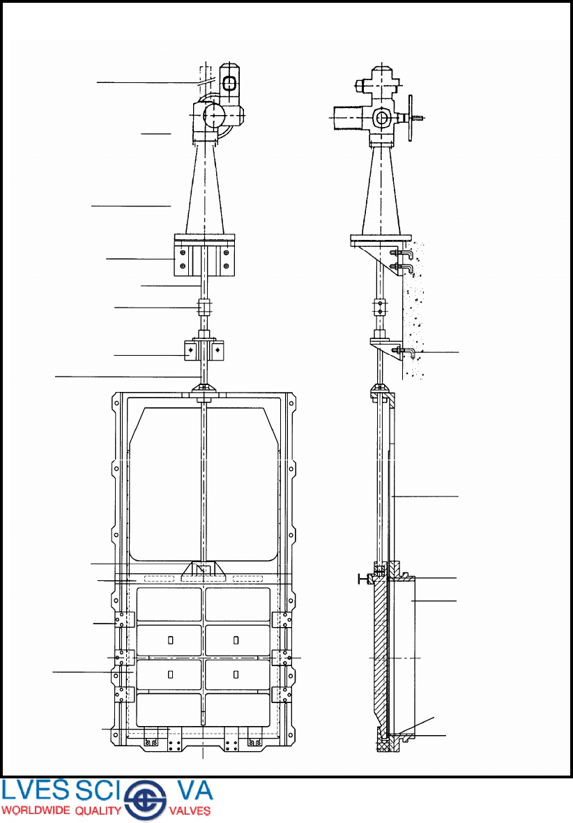
Its function is to support the gate and allow it to slide up and down while achieving a watertight seal. Cast iron sluice gate. The relevant seismic loads utilised in the design have been calculated using the methodology proposed by C.
EXAMPLE Sluice gate A sluice gate controls flow in open channels. V 2 Q A 2 Q b z 2. Neglecting bottom friction and atmos-pheric pressure decide the velocities 8 5 and 8 6 and the horizontal force re-quired to hold the gate if D 56 m D 61 m and L5 m.
The moveable part of the sluice gate. Finally we can solve the above equation for Q to find the flowrate through the sluice gate. I want to have your expert advices about a sluice gate design.
Considering a vertical sluice gate in a horizontal smooth rectangular channel the upstream and downstream water depths are respectively 51 and 045 m. A b V1t L CalculationsFor each water depth used determine the flowrate under the sluice gate by using the continuity equation Q QA11Vbz1V. Drive Mechanism This is the mechanism that drives the gate.
Slide 19 of 22. CALCULATE VELOCITY FLOW RATE FROM y1 y2. Slide 15 of 22.
Now that the v 1 and v 2 have been defined the above can be added to the Bernoulli equation. Wm H x L x W x D Eq. Eq 3 Q z.
It obstructs the passage of liquid when lowered and lets it pass when raised. For the opening of a 1-meter-high sluice gate the use of automatic design takes 3 minutes which previously takes 45 minutes. C-29 Plate C-13 Lower Gate Pintle Assembly Horizontally Framed Miter Gates.
I am new to this site and perhaps this is my first post. Discharge under a sluice gate. Y3 tailwater depth ie flow depth downstream of sluice gate under parallel flow.
Handwheel or motor to the gate. This automatic sluice gate will be able to open floodgates that weigh up to 3 tons with only a short time. To calculate the flow through a sluice gate you will need to use a combination of Bernoulli equation and the continuity equation.
Discharge under a sluice gate. I have attached a picture of that gate showing loadings and dimensions of gate. Y1 headwater depth ie flow depth upstream of sluice gate under parallel flow.
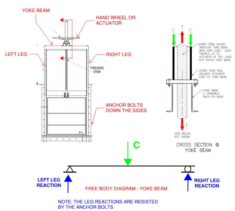
Self Contained Sluice Gate Actuator Stall Load Structural Engineering General Discussion Eng Tips
2
Sluice Gate Valve

Trapezoidal Screw Jack Mechanism 25ton For Sluice Gate Trapezoidal Screw Jack Mechanism 25ton For Sluice Gate Suppliers Manufacturers Factories
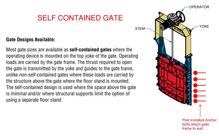
Self Contained Sluice Gate Actuator Stall Load Structural Engineering General Discussion Eng Tips

Manual Sluice Gate Pdf

Pdf Optimization Of Sluice Gate Under Fatigue Life Subjected For Forced Vibration By Fluid Flow
Sluice Gates Water Wind Wave Tank Hydrodynamic Testing Facility
0 comments
Post a Comment